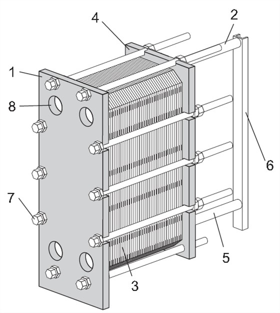
The plate heat exchanger is mainly composed of the following 8 parts:

1. Fixed clamping plate
Fixed plates with different numbers of interface holes for connecting to the piping system. Upper guide bar and lower guide bar
Connect to the fixed plate.
2. Upper guide rod
Carrying plate group and pressing plate.
3. Plate group
Heat is transferred from one medium to another through the plates. The plate group consists of grooved plates, end plates, and gaskets
And transition board (in some cases). The measurement data of the plate group is the size A, that is, the fixed plate and the pressure
Measurement data between tight plates. Refer to the drawing of the plate heat exchanger.
4. Active compression plate
The removable plate can contain various interface holes for connecting to the piping system.
5. Lower guide rod
Keep the bottom ends of the grooved plate, connecting plate and compression plate aligned.
6. Pillar
Support the upper and lower guide bars.
7. Fasten bolts
Press the plate group between the fixing plate and the pressing plate.
The bolts with bearing box are fastening bolts.
The remaining bolts are used as locking bolts.
8. Interface corner hole
The interface hole through the fixing plate allows the medium to enter or exit the heat exchanger.

In addition, we have some other optional parts. They are:
• Stud bolt
Threaded studs around the interface holes secure the flange joint to the device.
• Partition
Rugged carbon steel plates used in multi-process configurations. Reinforce the steering plate when needed.
• Support feet
Provides stability and is used to bolt the heat exchanger to the base.
• protecting mask
Cover the plate group to avoid high temperature or aggressive liquid leakage or (personnel) contact with the high temperature plate group.
• Bolt protector
A plastic tube used to protect the thread of the fastening bolt.
• Insulation
For applications where the temperature on the surface of the heat exchanger is too high or too low, an insulation layer can be used.
• Lifting device
A separate device installed on the heat exchanger for lifting the heat exchanger.
• Ground lug
The ground connection can be used to eliminate the risk of static buildup in the device.
• Interface cover
Protective device to avoid particles entering the heat exchanger during transportation.
• water tray
Depending on the type of fluid in the heat exchanger and the type of installation, a water tray (drain tank) may be required to avoid
Personal injury and equipment damage.
• Lifting or transporting fixtures
A locking device fixed between the fixing plate and the pressing plate.
The above is the most detailed explanation of the structure of the plate heat exchanger. If there are other structural problems, please pay attention to consult us.


 Food grade plate heat exchanger
 Plate And Shell Heat Exchanger